
An Easy-to-Follow Introduction to the Toffoli Gate
It's time to learn about another multi-qubit quantum gate called the Toffoli or CCNOT gate.


In the previous lessons on ‘Into Quantum’, we have explored multi-qubit quantum gates, such as the CNOT gate.

The CNOT gate is a two-qubit quantum gate where the control qubit determines whether the target qubit is flipped or not.
In this lesson, we will discuss another multi-qubit quantum gate called the Toffoli gate, which extends the CNOT gate by adding a second control qubit.
Let’s begin!

What is the Toffoli gate?
The Toffoli gate is also called the Controlled-Controlled-NOT (CCNOT) gate.
It is a three-qubit gate that receives three inputs and returns three outputs. The first two inputs are ‘Control qubits’, and the third input is the 'Target qubit’.
The gate flips the target qubit if and only if both control qubits are in the |1> state. Otherwise, it returns the target qubit unchanged. Also, the two control qubits are always returned unchanged.
There are two properties of the gate that you must know about:
It is reversible, which means that it is its own inverse.
If we apply the gate again to its outputs, we get the original inputs back, without losing any information.It is universal for classical computing, which means that we can build any logic circuit we want by connecting many Toffoli gates.
But in quantum computing, we need to combine the Toffoli with other gates to make it universal.
The gate was invented by and named after Tommaso Toffoli, an Italian-American professor of electrical and computer engineering at Boston University.
Toffoli Gate In Action
Take an example of the three qubits |A>,|B>,|C> input to the Toffoli gate, as shown below:

When the Toffoli gate is applied with |A> and |B> as the control qubits, and |C> as the target qubit, the outputs returned are:
Output 1 is
|1>
(Control qubit|A>is returned unchanged.)Output 2 is
|1>
(Control qubit|B>is returned unchanged.)Output 3 is
|1>
(|C>, previously|0>, is flipped because both control qubits|A>and|B>are|1>.)
This operation is represented as:

Truth Table
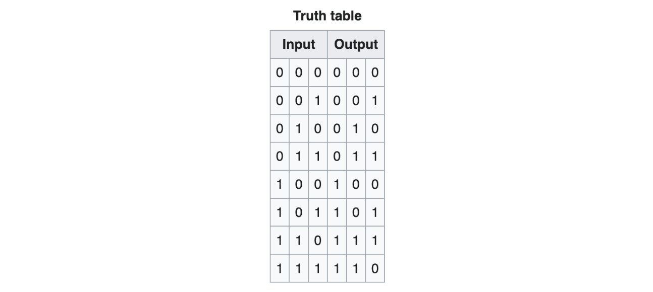
The truth table for the Toffoli gate is as follows.
Since each qubit can be |0> or |1>, there are 2³ = 8 possible inputs.
Circuit Symbol
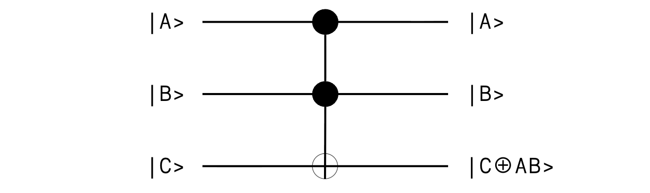
In a quantum circuit, the Toffoli gate is represented using the following symbol, where:
The ● symbol represents the control qubits.
The ⊕ symbol represents the target qubit and indicates that a NOT operation (Pauli-X) is applied to it conditionally.
Algebraic Representation
The operation performed by the Toffoli gate can be represented as:

where:
⊕ is the XOR (exclusive OR) operation, and
·is the multiplication (AND) operation
This means that the Toffoli gate computes the AND of the two control qubits and XORs the result with the target.
Matrix Representation
The Toffoli gate acts on a 3-qubit system, and is represented by a 2³ × 2³ = 8 × 8 unitary matrix as follows:
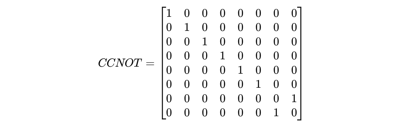
Note how only the last two rows (and columns) are swapped.
Consider the three qubits |A>,|B>,|C> again, which represent the inputs to the gate:
The combined input state to the Toffoli gate is:

The computational basis states for a 3-qubit system are:

On this basis:

When we apply the Toffoli gate to it, the following matrix multiplication takes place:
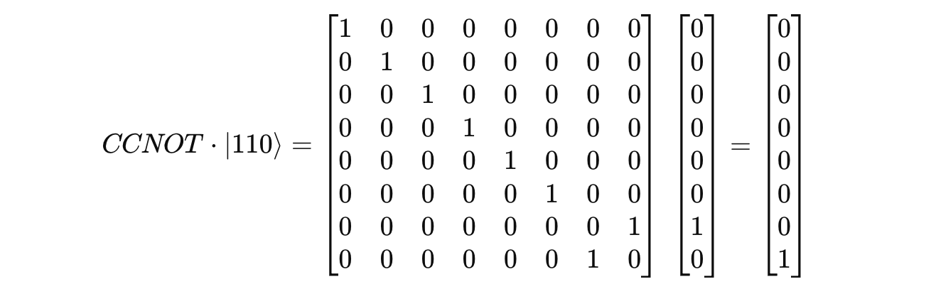
This result is equal to |111>.

That’s everything for this article.
Thanks for being a curious reader of ‘Into Quantum’, a publication that teaches essential concepts in Quantum Computing from the ground up.
To get even more value from this publication, consider becoming a paid subscriber.
